")
")
")
2.5. ILDA Streaming
ILDA Streaming - easily transmit ILDA over LAN
ILDA Streaming describes the transmission of the analog ILDA laser control signal over a digital network.
The ShowNET is capable of ILDA streaming: It requires a sender, which takes up the ILDA signal of another device, e.g. a USB interface, and transforms it to a digital signal in real time. Sender always needs to be an external ShowNET interface, as those have an ILDA inputn interface.
The receiver in an ILDA streaming environment can be any Laser with ShowNET mainboard or any external ShowNET device.
The transfer of the data via network works with a standard network protocol. Thus it is possible to use switches to split up the signal, transmit it via fibre or V-LAN or other common methods. This helps to get rid of long and bulky ILDA cables, but also allows for much longer signal transfer distances. So instead of having to run multiple ILDA lines from the FoH to the stage, it is only one network cable - even for multiple laser systems!
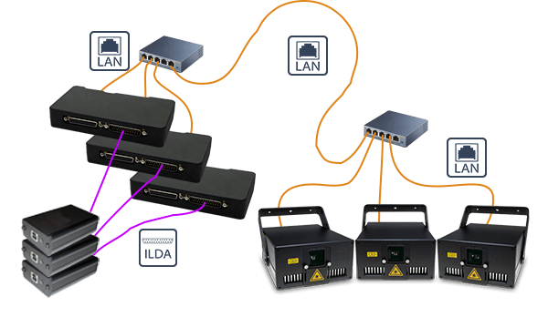
1. Understand the wiring scheme:
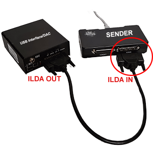
2. The ILDA signal, that comes from any ILDA DAC (USB DAC, Lasergraph DSP, FB3, etc.) is connected with a short ilda cable to the ILDA IN of an external ShowNET device.
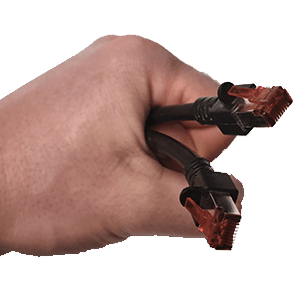
3. Use standard LAN-cable (Ethernet-cable), minimum of standard CAT-5 (most cables are), and connect the ShowNET interface to the target Laser with integrated ShowNET Laser mainboard or another external ShowNET. The LAN cable can be very long, the signal can be distributed with standard network switches, can be transmitted over fibre or V-LAN, etc. ... just like a normal network signal.
The ShowNET is capable of ILDA streaming: It requires a sender, which takes up the ILDA signal of another device, e.g. a USB interface, and transforms it to a digital signal in real time. Sender always needs to be an external ShowNET interface, as those have an ILDA inputn interface.
The receiver in an ILDA streaming environment can be any Laser with ShowNET mainboard or any external ShowNET device.
The transfer of the data via network works with a standard network protocol. Thus it is possible to use switches to split up the signal, transmit it via fibre or V-LAN or other common methods. This helps to get rid of long and bulky ILDA cables, but also allows for much longer signal transfer distances. So instead of having to run multiple ILDA lines from the FoH to the stage, it is only one network cable - even for multiple laser systems!
Connection scheme:
1. Understand the wiring scheme:
2. The ILDA signal, that comes from any ILDA DAC (USB DAC, Lasergraph DSP, FB3, etc.) is connected with a short ilda cable to the ILDA IN of an external ShowNET device.
3. Use standard LAN-cable (Ethernet-cable), minimum of standard CAT-5 (most cables are), and connect the ShowNET interface to the target Laser with integrated ShowNET Laser mainboard or another external ShowNET. The LAN cable can be very long, the signal can be distributed with standard network switches, can be transmitted over fibre or V-LAN, etc. ... just like a normal network signal.
Configure Sender and Receiver Device
The Sender ShowNET device has to be an external ShowNET interface. The external ShowNET interface has an ILDA input port, where the ILDA laser control signal of another Laser DAC, e.g. a Pangolin FB3 or a Lasergraph DSP, can be feeded in. This can be done with a short ILDA cable.
The Sender ShowNET then needs to be assigned a specific IP address, so it can directly communicate with the related receiver device later. It is always a pre-defined pair of sender and receiver that communicate with each other.<br
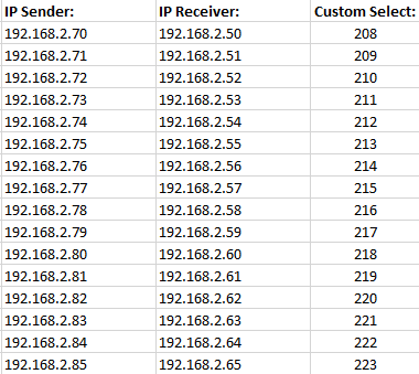
This is the address chart that shows the correlation between sender and receiver. It also shows how the address setting has to be done:
Important:
Like in any IP based network, each device in the network MUST have an individual IP address! It is NOT possible that any device has the same IP address, this will lead to conflicts!
So Sender and Reciever are always a pair - it is not possible to have one Sender sending it's signal to two Receivers. To achieve that, use a Y-Splitter on the ILDA signal before feeding it to the Senders and use two Sender-Receiver-pairs.
The sender uses an IP address range between 192.168.2.70 and 192.168.2.85 and transmits the signal to a receiver that has addresses in the range between 192.168.2.50 and 192.168.2.65. The specific IP addresses need to be set at the display. Make sure there are no other devices in the same network that use the same IP addresses.
Power off/power on the Laser to make the settings effective.
Power off/power on the Laser to make the settings effective.
The Sender ShowNET then needs to be assigned a specific IP address, so it can directly communicate with the related receiver device later. It is always a pre-defined pair of sender and receiver that communicate with each other.<br
This is the address chart that shows the correlation between sender and receiver. It also shows how the address setting has to be done:
Important:
Like in any IP based network, each device in the network MUST have an individual IP address! It is NOT possible that any device has the same IP address, this will lead to conflicts!
So Sender and Reciever are always a pair - it is not possible to have one Sender sending it's signal to two Receivers. To achieve that, use a Y-Splitter on the ILDA signal before feeding it to the Senders and use two Sender-Receiver-pairs.
The sender uses an IP address range between 192.168.2.70 and 192.168.2.85 and transmits the signal to a receiver that has addresses in the range between 192.168.2.50 and 192.168.2.65. The specific IP addresses need to be set at the display. Make sure there are no other devices in the same network that use the same IP addresses.
Configure the Laser as ILDA Streaming Sender
- Press the rotary dial, so the text is not marked in green any more
- Turn the rotary dial until Custom select is selected:
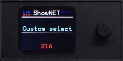
- Press the rotary dial to activate the value selection
- Specify the Custom value from the submenu to match the IP address according to below list and press the rotary dial to confirm the selection
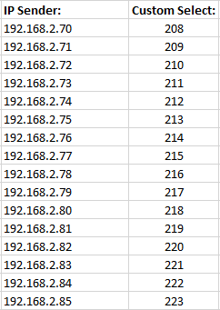
- The Custom Value is marked in green to show that it's active. The laser has now been assigned a specific Sender IP address
Power off/power on the Laser to make the settings effective.
Configure the Laser as ILDA Streaming receiver
Set the Display to LAN->ShowNET using the rotary dial to make the receiver settings:- Press the rotary dial, so the text is not marked in green any more
- Turn the rotary dial until the LAN->ShowNETmode is selected:
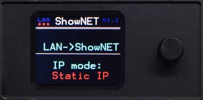
- Press the rotary dial to activate the LAN->ShowNET Mode
- Select Static IP from the submenu und press the rotary dial to confirm the selection and open the IP setting submenu
- Use the rotary dial to specify the static IP address - for ILDA streaming operation it must be an IP address in the range of 192.168.2.x
- Press the rotary dial to confim the settings, the text should be marked in green to show the active state. The laser is now in ILDA streaming receiver mode.
Power off/power on the Laser to make the settings effective.